Electronic Ballast Block Diagram
General Block Diagram of Electronic Ballasts. It does this through the principle of electrical gas discharge.
Electronic X Ballast Circuit Diagram

1 Electronic ballast block diagram.

Electronic ballast block diagram. The boost converter which regulates the output voltage and performs the power factor correction. ELECTRONIC BALLAST Block Diagram details for FCC ID N96120332ISMPF made by Sunpark Electronics Corp. Https Www St Com Resource En Application Note Cd00192161 Pdf.
Design of Electronic Ballasts Eric Persson Exec. Ebhpfcon Electronic Ballast Block Diagram Kai Wo Trading Co Various Schematics And Diagrams Off Line Led Control Circuit Led Professional Led Eec247 Information On Compact Fluorescent Lighting International Rectifier Ltd Irs Hvics Lead The Way High Power Electronic Ballasts For Medium Pressure Uv Lamps A Block Diagram Of The Conventional Electronic Ballast Electronic Ballast. Electronic ballasts with dedicated drivers and controllers.
Diagram circuit diagram of electronic ballast full version hd quality electronic ballast. Fluorescent Ballast Wiring Diagram 8 foot fluorescent ballast wiring diagram advance fluorescent ballast wiring diagram compact fluorescent ballast wiring diagram Every electric arrangement is composed of various diverse pieces. It reveals the components of the circuit as streamlined forms and also the power and signal connections in.
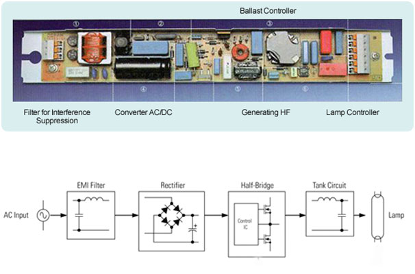
With such an illustrative guide you will be able to troubleshoot avoid and complete your projects easily. An electronic ballast will convert power frequency to a very high frequency to initialize the gas discharge process in Fluorescent Lamps. The simple block diagram of the electronic ballast is given below.
The input filter is used to attenuate the electromagnetic interference EMI generated by the. Generally all the electronic ballasts follows that block diagram. This application note describes an electronic ballast that is ab le to recognize lamps within the T5 fluorescent family.
Each component ought to be placed and connected with different parts in particular manner. Simple electronic fuse circuit. COMPANY CONFIDENTIAL Gas Discharge Lamp Basics 3 Low Pressure Fluorescent Lamp Current flows through plasma.
219 shows the general block diagram of a typical electronic ballast. Figure 229 shows the general block diagram of a typical electronic ballast. The ballast takes advantage of a characteristic of fluorescent lamp whereby greater luminous efficacy please click for definition is obtained at high operating frequency above 20kHz.
The input filter is used to attenuate the electromagnetic interference EMI generated by the high. Document Includes Block Diagram Block Diagram. Director WW Field Applications Engineering April 17 2009.
This filter is mandatory for commercial electronic ballast. Instead of havi ng a dedicated circuit for each lamp with a single ballast it is possible to drive many different lamp groups. Block diagram indicating main functions of electronic ballast How it can save energy how much energy can be saved.
The complete circuit is composed of two stages. Today thanks to microcontrollers it is possible to add intelligence into the circuit. The main stages are the following.
The half-bridge driver operates at a given frequency with a 50 duty cycle and a fixed non-overlapping dead-time. Aug 6 2019 - You may notice when we use electronic ballast with fluorescent light then the fluorescent light does not need any starter but when we use electrical choke then the fluorescent light need a starter but why lets discuss. Ballast wiring diagram You will need a comprehensive professional and easy to comprehend Wiring Diagram.
The main stages are the following. Touch device users explore by touch. When autocomplete results are available use up and down arrows to review and enter to select.
COMPANY CONFIDENTIAL Agenda Gas-Discharge lamps ZVS Resonant Half-Bridge output stage Typical ballast designs PFC Protection features Summary 2. A wiring diagram is a streamlined traditional pictorial representation of an electric circuit. The block diagram of the ballast is shown in Figure 8.
General Block Diagram of Electronic Ballasts. The inverter stage composed of a full bridge that converts the DC current coming from the PFC stage into an AC current for the lamp. Usually it consists of two coupled inductors and a capacitor.
Control Circuits The half-bridge resonant output stage is necessary for each ballast topology and is controlled with a voltage-controlled oscillator VCO input and a high- and low-side half-bridge driver output Figure 2. Simple control circuits for electronic ballast design. Block 1 represents the.
Not only will it assist you to attain your desired outcomes quicker but in addition make the complete procedure simpler for everybody. April 27 2018 by headcontrolsystem Assortment of electronic ballast wiring diagram. This filter is mandatory for commercial electronic ballast.
Currently some electronic ballasts have appeared on the market and Table 1 lists the performance comparison of these electronic ballasts. According to the International Electrotechnical Commission standard IEC929 and Chinas professional standard ZBK74012-90 the electronic ballast should be used in normal conditions the lamp should be activated but it does not cause damage to. An electronic ballast or electrical ballast is a device which controls the starting voltage and the operating currents of lighting devices.
As you see in the above figure there are a total of five blocks in the block diagram of the electronic ballast. Otherwise the structure wont function as it ought to be. Usually it consists of two coupled inductors and a capacitor.
Diagram circuit diagram of electronic ballast full version hd quality electronic ballast.
4pkefa14e28 Electronic Ballast For Compact Fluorescent Lamp Block Diagram Block And Schematic Efa Series Panasonic
A Block Diagram Of The Conventional Electronic Ballast With Output Download Scientific Diagram
Block Diagram Of The Digital Dimming Electronic Ballast Download Scientific Diagram

Block Diagram Of An Electronic Ballast Download Scientific Diagram

Block Diagram Of Electronic Ballast For T8 T5 Adaptor Download Scientific Diagram

Electronic Ballast Working Principle Circuit Diagram Electrical4u
Explained Electronic Ballast Circuit Diagram And Working Etechnog

Electronic Ballast Working Principle Circuit Diagram Electrical4u

Fluorescent Lamp Electronic Ballast 5 Circuit Diagram Electronics Ballast

Electronic Ballast
The Block Diagram Of The Electronic Ballast For Powering The Uv Download Scientific Diagram

Explained Electronic Ballast Circuit Diagram And Working Etechnog

Figure 1 From Simple Control Circuits For Electronic Ballast Design Semantic Scholar

Explained Electronic Ballast Circuit Diagram And Working Etechnog

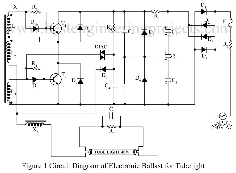
Electronic Ballast Circuit Engineering Projects
Block Diagram Of An Electronic Ballast Download Scientific Diagram

Electronic Ballast For Fluorescent Lamp Patent 0831677
Typical Compact Flash Lamp Ballast Circuit 10 15 Compact Fluorescent Download Scientific Diagram

4pkefa14e28 Electronic Ballast For Compact Fluorescent Lamp Block Diagram Block And Schematic Efa Series Panasonic


Post a Comment for "Electronic Ballast Block Diagram"